Remote Handling Robotic Arm for Hazardous Environments

Problem

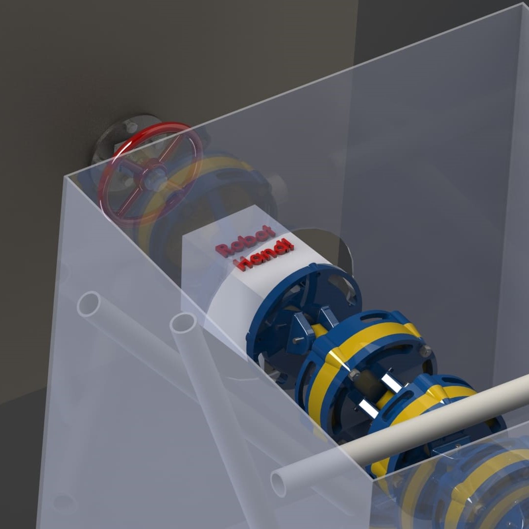
The Naval Nuclear Lab (NNL) partnered with my team composed of four mechanical engineering students to work on part of their multi-semester project. This project's mission centered on the development of an unmanned apparatus for handling hazardous material safely and reliably within a confined and cramped space. This was a continuation of previous steps that had been tackled. The problem scenario included navigating this robot through a 2'x2' array filled with random clutter visualized by the PVC pipe in the CAD image below.

2' x 2' array scope of the problem tackled

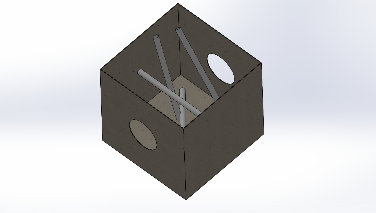
We selected to work on designing an arm segment or sometimes referred to as a "macroscopic manipulator", leaving the "microscopic manipulator", or end effector, to a following team. Below, the outline of the problem is written and visualized in the pdf where the supplementary picture on the left is taken from.


Approach

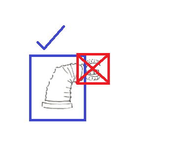
As the team explored design options, the constraints became the clear guides of our design; the ability to easily manufacture, maintenance and dispose were all important considerations that we could not ignore in our analysis when choosing a final design path.

The PDF right below shows some early reasoning and drafting before we met with our sponsors for input on the refinement of our ideas which were refined upon hearing some of the other constraints we learned to consider later.


The need to easily dispose of a radiated bot meant that pneumatics and hydraullics were off the table according to our client, so we instead opted to pursue electric motors with a a gearset transmission. Due to the required flexibility required by the obstacles in the array, our design would preserve the "snake-like" or "trunk-like" intention from the original design, but instead use a series of motors to provide motion through a series of segmented parts.

Below a few of the early concepts were drawn out once the category of actuator was agreed to be some sort of motor, and other, shown as a concept as a final arm enclosed in a sheath of some kind for environmental protection.

In the train of joints, each member had 2 degrees of freedom. One to rotate the yaw (around the linkage axis) and the other would change the pitch which would move the top plate. It can be imagined as a series of https://en.wikipedia.org/wiki/Lazy_Susan combined with an electric linear actuator to 'tip' the plate to a desired angle.

Concept visual for arm Early approach Second iteration

Analysis

The main focus of our team was with developing a usable "skeleton" for the next team who would be able to add actuators and control systems. The first order of business was to assess the static strength of what we created under maximum loading. To find out how it fails, we just need to take it at the weakest point, or the point with the greatest load and determine if it passes its maximum strength. So we chose to make the arm extend over its supports in the maximum loading range; a total horizontal fully-stretched cantilever. This way, we could model the arm as a cantilever load which reduces the problem to a 1-dimensional beam-in-bending which experiences the stress of self-weight, an end-load and a torsional load from the gripper. This simplifies what we have to consider and calculate tremendously all while being generous in loading the part beyond what it will see in the design scenario.

Below, I included a brief analysis showing the results mocked up in ANSYS in a static-structural simulation to demonstrate the stresses, strains, and deformation experience by the maximally loaded part assumed to be the plate holding the rest of the arm horizontal.

juxtaposed arm with cantilever idealization

The next step was to load a geometry and assign material properties to a model which belonged to the top plate with a mesh refinement at the hinges. The simulation results are shown for the deformation and for the displacement

Note: At the time it was simulated, the student license denied the ability to simulate with more elements and a better mesh, so the resulting simulation was simpler than the design scenario called for and in more time, a better simulation would be ideal.

juxtaposed arm with cantilever idealization juxtaposed arm with cantilever idealization

It can be seen from the plots that the areas experiencing the highest deformation are essentially "opposite" plots of the areas of highest stress. This passes a sanity check since we can return to our beam model to think if the end of a beam is deformed majorly, the resulting stress accumulates at the "last link" in the structure so that thats where the greatest stress should be found. The preliminary (and final) report is shown below for more detail.


Results

We delivered a 3D CAD model with accompanying engineering drawings. Although we did not get to create a prototype since the end of the project was completed at the start of the COVID-19 outbreak, we would most likely have 3D-printed our model and ordered the stock parts form McMaster-Carr. We also delivered the simulation results, a design justification, a report on radiation hardening and a final presentation. Included a link to the mechanical drawings done at the very end which did not undergo revision or feedback.

Here are some renders of a single segment which were rendered at the completion of the design with a few stock hardware pieces from McMaster Carr like the screws and needle bearings.

juxtaposed arm with cantilever idealization